CONVENTIONAL (HEAT + AC) 4 WIRES
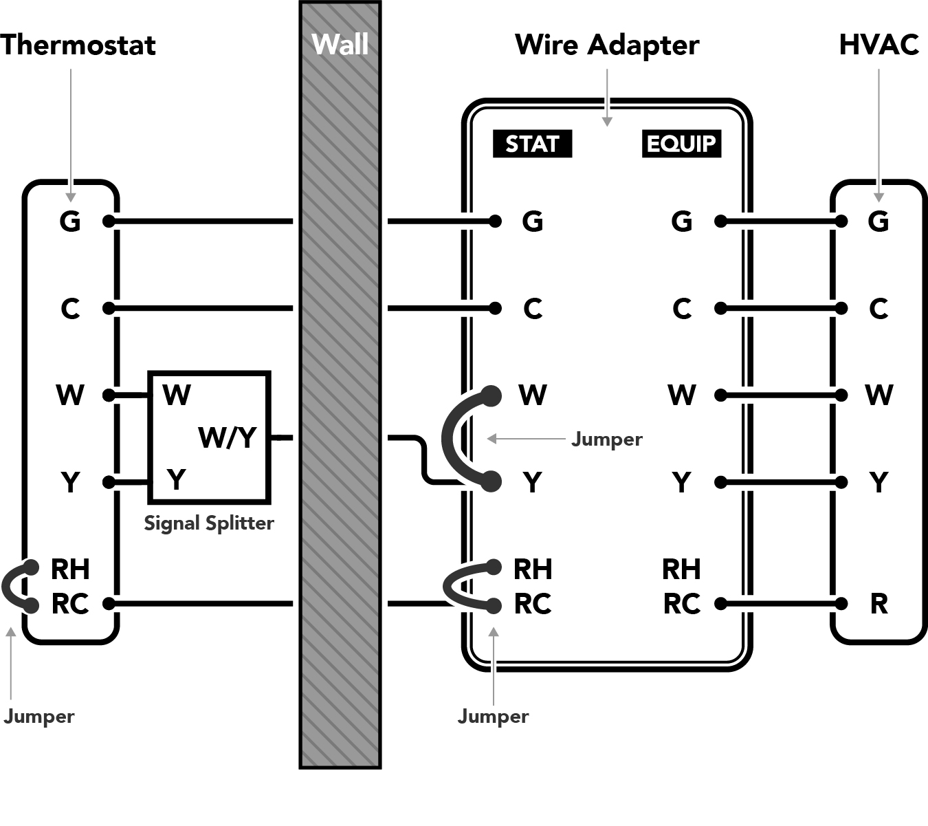 AT THE FURNACE OR HVAC SYSTEM:
- Connect the RC, Y, W, C, and G terminals on the EQUIP side of the Wire Adapter to the corresponding terminals on the HVAC control board. Use the provided length of wire if necessary.
- Connect the existing R and G wires (that come from the Thermostat) to the RC and G terminals on the STAT side of the Wire Adapter. Leave the Jumper in place between RC-RH. Note: If the system does not have a G wire, do not connect any of the G terminals.
- Connect one of the remaining two wires (that come from the Thermostat) to the Y terminal on the STAT side of the Wire Adapter. Leave the Jumper in place between W-Y.
- Connect the last remaining wire (that comes from the Thermostat) to the C terminal on the STAT side of the Wire Adapter.
- Cap or tape the ends of any unused wires.
Note: Any additional wires not shown on the diagram can be routed around the wire adapter, directly from the HVAC system to the Thermostat.
AT THE THERMOSTAT:
- Connect the R and G wires coming from the wall to the RC and G terminals on the Thermostat. Leave the Jumper in place between RC-RH. Note: If the system does not have a G wire, do not connect anything to the G terminal.
- Find the end of the wire you selected in step 3 above, insert it into the screw clamp on the Signal Splitter, and tighten the screw. Connect the W leg of the Signal Splitter to the W terminal of the Thermostat, and the Y leg of the Signal Splitter to the Y terminal of the Thermostat.
- Connect the wire you selected in step 4 above to the C terminal of the Thermostat.
- Arrange the wires to fit in the recess in the rear of the Thermostat, and press the Thermostat into place on the mounting plate. Be sure that there are no bare wires in contact with each other.
CONVENTIONAL (HEAT + AC) 5 WIRES
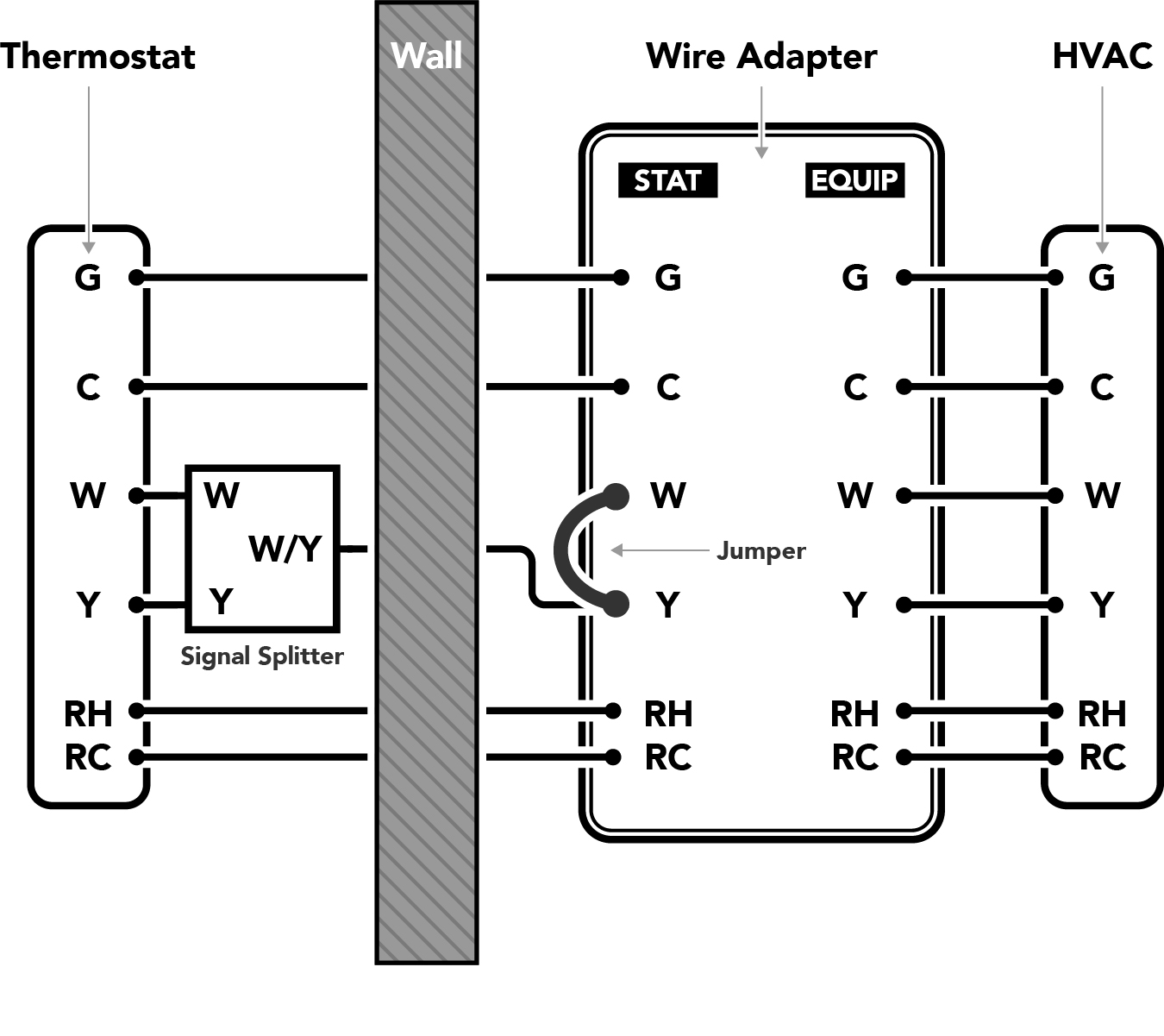 AT THE FURNACE OR HVAC SYSTEM:
- Connect the RC, RH, Y, W, C, and G terminals on the EQUIP side of the Wire Adapter to the corresponding terminals on the HVAC control board. Use the provided length of wire if necessary.
- Connect the existing RC, RH, and G wires (that come from the Thermostat) to the RC, RH, and G terminals on the STAT side of the Wire Adapter. Remove the Jumper between RC-RH. Note: If the system does not have a G wire, do not connect any of the G terminals.
- Connect one of the remaining two wires (that come from the Thermostat) to the Y terminal on the STAT side of the Wire Adapter. Leave the Jumper in place between W-Y.
- Connect the last remaining wire (that comes from the Thermostat) to the C terminal on the STAT side of the Wire Adapter.
- Cap or tape the ends of any unused wires.
Note: Any additional wires not shown on the diagram can be routed around the wire adapter, directly from the HVAC system to the Thermostat.
AT THE THERMOSTAT:
- Connect the RC, RH, and G wires coming from the wall to the RC, RH, and G terminals on the Thermostat. Remove the Jumper between RC-RH. Note: If the system does not have a G wire, do not connect anything to the G terminal.
- Find the end of the wire you selected in step 3 above, insert it into the screw clamp on the Signal Splitter, and tighten the screw. Connect the W leg of the Signal Splitter to the W terminal of the Thermostat, and the Y leg of the Signal Splitter to the Y terminal of the Thermostat.
- Connect the wire you selected in step 4 above to the C terminal of the Thermostat.
- Arrange the wires to fit in the recess in the rear of the Thermostat, and press the Thermostat into place on the mounting plate. Be sure that there are no bare wires in contact with each other.
CONVENTIONAL (HEAT + FAN)
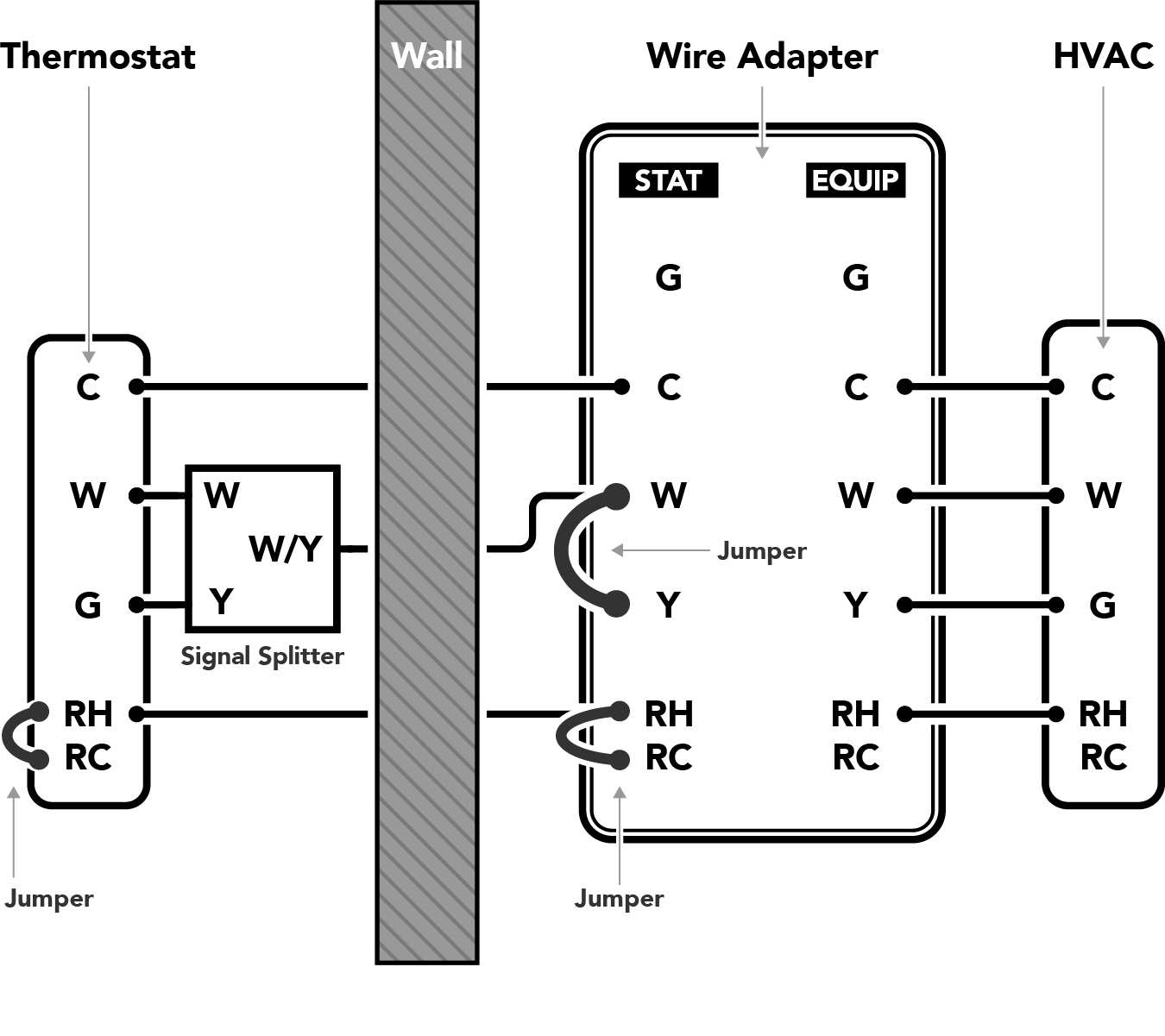 AT THE FURNACE OR HVAC SYSTEM:
- Connect the R, W, and C terminals on the EQUIP side of the Wire Adapter to the corresponding terminals on the HVAC control board. Connect the G terminal on the HVAC board to the Y terminal on the Wire Adapter. Use the provided length of wire if necessary.
- Connect the existing R wire (that comes from the Thermostat) to the RH terminal on the STAT side of the Wire Adapter. Leave the Jumper in place between RC- RH.
- Connect one of the remaining two wires (that come from the Thermostat) to the W terminal on the STAT side of the Wire Adapter. Leave the Jumper in place between W-Y.
- Connect the last remaining wire (that comes from the Thermostat) to the C terminal on the STAT side of the Wire Adapter.
Note: Any additional wires not shown on the diagram can be routed around the wire adapter, directly from the HVAC system to the Thermostat.
AT THE THERMOSTAT:
- Connect the R and G wires coming from the wall to the RH and G terminals on the Thermostat. Leave the Jumper in place between RC-RH.
- Find the end of the wire you selected in step 3 above, insert it into the screw clamp on the Signal Splitter, and tighten the screw. Connect the W leg of the Signal Splitter to the W terminal of the Thermostat, and the Y leg of the Signal Splitter to the G terminal of the Thermostat.
- Connect the wire you selected in step 4 above to the C terminal of the Thermostat.
- Arrange the wires to fit in the recess in the rear of the Thermostat, and press the Thermostat into place on the mounting plate. Be sure that there are no bare wires in contact with each other.
CONVENTIONAL (AC + FAN)
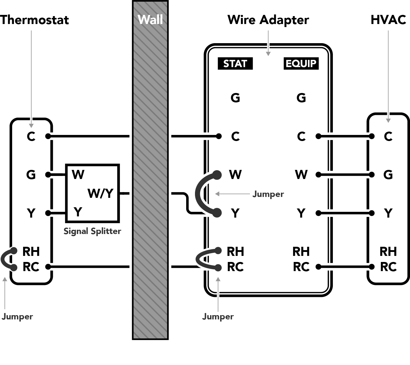 AT THE FURNACE OR HVAC SYSTEM:
- Connect the R, Y, and C terminals on the EQUIP side of the Wire Adapter to the corresponding terminals on the HVAC control board. Connect the G terminal on the HVAC board to the W terminal on the Wire Adapter. Use the provided length of wire if necessary.
- Connect the existing R wire (that comes from the Thermostat) to the RC terminal on the STAT side of the Wire Adapter. Leave the Jumper in place between RC- RH.
- Connect one of the remaining two wires (that come from the Thermostat) to the Y terminal on the STAT side of the Wire Adapter. Leave the Jumper in place between W-Y.
- Connect the last remaining wire (that comes from the Thermostat) to the C terminal on the STAT side of the Wire Adapter.
Note: Any additional wires not shown on the diagram can be routed around the wire adapter, directly from the HVAC system to the Thermostat.
AT THE THERMOSTAT:
- Connect the R and G wires coming from the wall to the RH and G terminals on the Thermostat. Leave the Jumper in place between RC-RH.
- Find the end of the wire you selected in step 3 above, insert it into the screw clamp on the Signal Splitter, and tighten the screw. Connect the W leg of the Signal Splitter to the W terminal of the Thermostat, and the Y leg of the Signal Splitter to the G terminal of the Thermostat.
- Connect the wire you selected in step 4 above to the C terminal of the Thermostat.
- Arrange the wires to fit in the recess in the rear of the Thermostat, and press the Thermostat into place on the mounting plate. Be sure that there are no bare wires in contact with each other.
HEAT PUMP SYSTEM
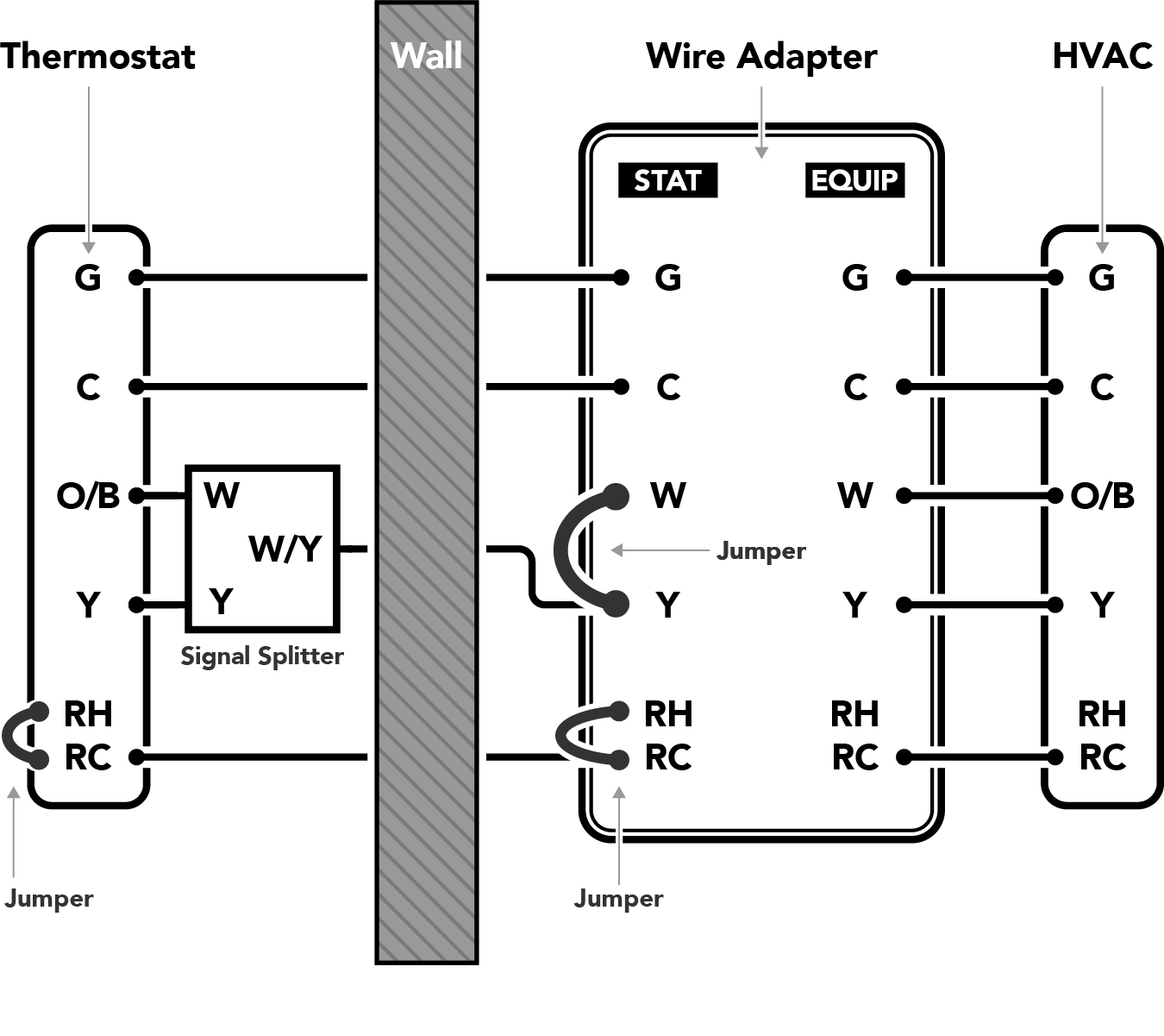
AT THE FURNACE OR HVAC SYSTEM:
- Connect the RC, Y, C, and G terminals on the EQUIP side of the Wire Adapter to the corresponding terminals on the HVAC control board. Connect the O/B (or O, or B) wire on the HVAC control board to the W terminal of the Wire Adapter. Use the provided length of wire if necessary.
- Connect the existing R and G wires (that come from the Thermostat) to the RC and G terminals on the STAT side of the Wire Adapter. Leave the Jumper in place between RC-RH. Note: If the system does not have a G wire, do not connect any of the G terminals.
- Connect one of the remaining two wires (that come from the Thermostat) to the Y terminal on the STAT side of the Wire Adapter. Leave the Jumper in place between W-Y.
- Connect the last remaining wire (that comes from the Thermostat) to the C terminal on the STAT side of the Wire Adapter.
- Cap or tape the ends of any unused wires.
Note: Any additional wires not shown on the diagram can be routed around the wire adapter, directly from the HVAC system to the Thermostat.
AT THE THERMOSTAT:
- Connect the R and G wires coming from the wall to the RC and G terminals on the Thermostat. Leave the Jumper in place between RC-RH. Note: If the system does not have a G wire, do not connect anything to the G terminal.
- Find the end of the wire you selected in step 3 above, insert it into the screw clamp on the Signal Splitter, and tighten the screw. Connect the W leg of the Signal Splitter to the O/B terminal of the Thermostat, and the Y leg of the Signal Splitter to the Y terminal of the Thermostat.
- Connect the wire you selected in step 4 above to the C terminal of the Thermostat.
- Arrange the wires to fit in the recess in the rear of the Thermostat, and press the Thermostat into place on the mounting plate. Be sure that there are no bare wires in contact with each other.